
Summary: Power electronics converter topologies are important for offboard EV fast charging applications. Learn more about the different AC-DC converter topologies used in EV fast charging in this technical article.
Greenhouse gas emissions from transportation alone account for 29% of the total emissions in the US. Therefore, the government, industry, and academia are prompted to develop alternative transportation solutions. As such, EVs are seen as the next revolution in the transportation sector to fight climate change. But the major problem seen with the adoption of EVs is the range anxiety that it offers.
Building a robust EV charging ecosystem that facilitates fast and ultra-fast charging solutions is a way to achieve 100% e-mobility in the future. The EV charging ecosystem also helps integrate renewable energy sources, which further helps in reducing greenhouse gas emissions. It also helps achieve peak load shaving and reactive power support with the utility grid. As seen in Figure 1, recent years have also witnessed a growing number of EV chargers installed, which cater to both slow and fast charging.
The design of EV fast chargers is of prime importance when considering the EV's battery life and charging time. An ideal EV charger's necessary features include high efficiency and high reliability. Such a charger should be affordable and carry low volume and size. When connected to the utility grid, the EV charger should draw current at a high power factor and very low THD (<5%).

Figure 1. Total publicly available EV chargers, including fast chargers (>22kW) and slow chargers (<22kW). Image used courtesy of M. Safayatullah et al.
State-of-the-art EV Charging
An EV charging station houses the necessary infrastructure to charge multiple EVs simultaneously. They are mini electrical grids in themselves and can be found in residential homes, industrial places, and many commercial places. The charging of EVs happens either via ac charging or DC charging. There are three different levels of charging the EVs as well, depending on the category of the EV that needs to be charged.
Level-1 and Level-2 charging take place with an AC power source, usually for lightweight EVs. Such EVs have these charges built-in within the vehicle itself and are referred to as onboard chargers. A regular 120/230 V ac is enough to supply the EVs via these onboard chargers, and they do not exceed a power rating of 20kW. On the other hand, the Level-3 type utilizes DC power directly from the source to charge the battery. Such a type of charger is called an offboard charger. It is worth noting that a Level-3 type of charging bypasses the onboard charger and feeds directly to the battery in the EV.
Figure 2 illustrates how the connection to the battery differs between onboard and offboard chargers. The power conversion in an EV DC fast charging station happens via a dedicated Electric Vehicle Supply Equipment (EVSE). The fast chargers, situated outside the EV, should be able to supply 100 V to 800 V regulated DC output voltage. Additionally, it should have the capability to charge the EV battery in less than 30 minutes to reach a battery SoC of 80% for 20 kWh to 40 kWh battery capacity.
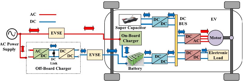
Figure 2. Electric vehicle (EV) charging system, including offboard and onboard chargers. Image used courtesy of M. Safayatullah et al.
Topologies for AC-DC Conversion Stage
The AC-DC converter of an offboard charger is a front-end rectifier before the DC-DC conversion stage of the complete EV fast charging station. Various topologies are available that convert AC power from the utility grid to DC power. Such topologies are expected to handle high power fed directly to the battery as part of an EV fast charging solution. Please note that DC-DC converters that follow the AC-DC converters are not part of this technical article.
1. Three-phase buck type rectifier
Three-phase buck type rectifier (TPBR) has high efficiency and can achieve power factor correction at a very low THD. The TPBR is also high in power density, making it an ideal converter topology as a front-end rectifier. This topology offers no inrush current during the startup and can provide overcurrent protection when a short circuit is detected. Figure 3 shows the TPBR converter topology with six switches and a freewheeling diode. A fundamental drawback with TPBR is that the input current is distorted during light load conditions. This is primarily attributed to the parasitic capacitance between the ground and the DC link output.
A single TPBR is a good converter while charging an EV. But when multiple EVs are to be charged, using a single TPBR will decrease the power quality. This is primarily due to the modulation index of a single TPBR reaching below 0.5. In such a case, multiple TPBRs can be grouped to form a matrix-type TPBR. Such a structure allows for the stable charging of multiple EVs simultaneously without losing power quality.
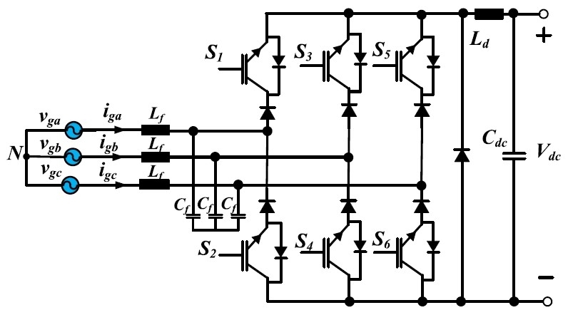
Figure 3. Three-phase six switch buck type rectifier. Image used courtesy of M. Safayatullah et al.
2. Swiss rectifier
The TPBR has a significant and advanced variant of itself, popularly known as the Swiss rectifier, shown in Figure 4. The Swiss rectifier has many advantages over its predecessor, such as higher efficiency and reduced common-mode noise. The Swiss rectifier has two additional switches over TPBR, reducing conduction and switching losses. Multiple Swiss rectifiers can be interleaved together, which allows for a smaller current and voltage ripple. Such interleaved structure leads to high reliability because of the increased number of semiconductor switches; thus, the failure rate is reduced.
High bandwidth, high power, and lower filter requirements are additional features of an interleaved Swiss rectifier. Despite the mentioned advantages, the Swiss rectifier only allows for a unidirectional power flow. A bidirectional power is possible but comes with additional semiconductor components and a complex control mechanism.
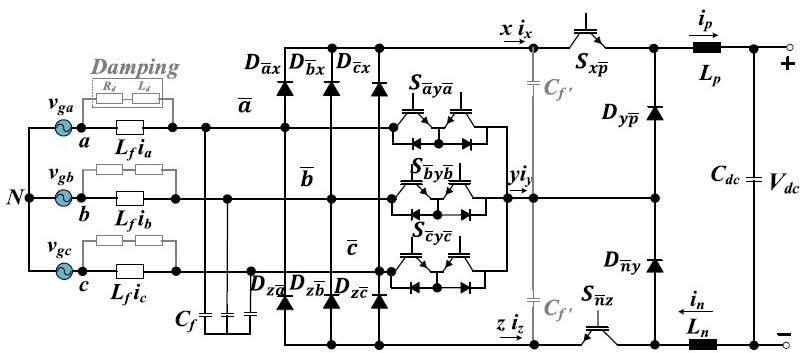
Figure 4. Swiss rectifier. Image used courtesy of M. Safayatullah et al.
3. Vienna rectifier
A three-phase Vienna rectifier, shown in Figure 5, consists of three inductors at the input, which helps to boost the incoming voltage. Followed by that is six diodes for rectification and six semiconductor switches. At the output, two split capacitors are added as well. Its operation is similar to a conventional three-phase boost PFC rectifier but does not support a bidirectional power flow. The Vienna rectifier has a simple control mechanism with unity power factor operation and a smaller THD. It operates with very high efficiency even for a power-dense application; therefore, it is well suited for high-power applications such as fast charging of EVs.
The Vienna rectifier can be made bidirectional by replacing the diodes with switches. This will ensure that power flows in either direction, which is very useful in Vehicle-2-Grid applications. The Vienna rectifiers primarily work on modulation methods such as carrier-based PWM, Space Vector PWM, and discontinuous PWM. In the case of interleaved Vienna rectifiers, Space Vector PWM will lead to distortions in the input current waveforms. The other two PWM techniques cause large undesirable ripples. Hence, hybrid Space Vector PWM is employed to overcome the aforementioned problems.
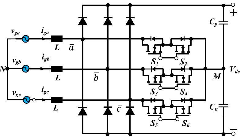
Figure 5. Three-phase Vienna rectifier. Image used courtesy of M. Safayatullah et al.
4. Three-phase boost type rectifier
The three-phase six switch boost type rectifier (TPSSBR) shown in Figure 6 has a basic structure and supports bidirectional power flow. The input current is continuous with a high DC voltage at the output. The individual ac source is connected with an inductor to carry out the boost operation, resulting in reduced harmonics in the input current. The six switches are arranged as two switches per leg, and the switches in each leg operate in a complimentary fashion. A drawback with this topology is that the antiparallel diodes in each semiconductor switch undergo reverse recovery loss, further deteriorating the switching loss of the MOSFETs. A possible solution to this problem is integrating an ultra-fast DC rail diode at the DC-link side to mitigate the reverse recovery loss.
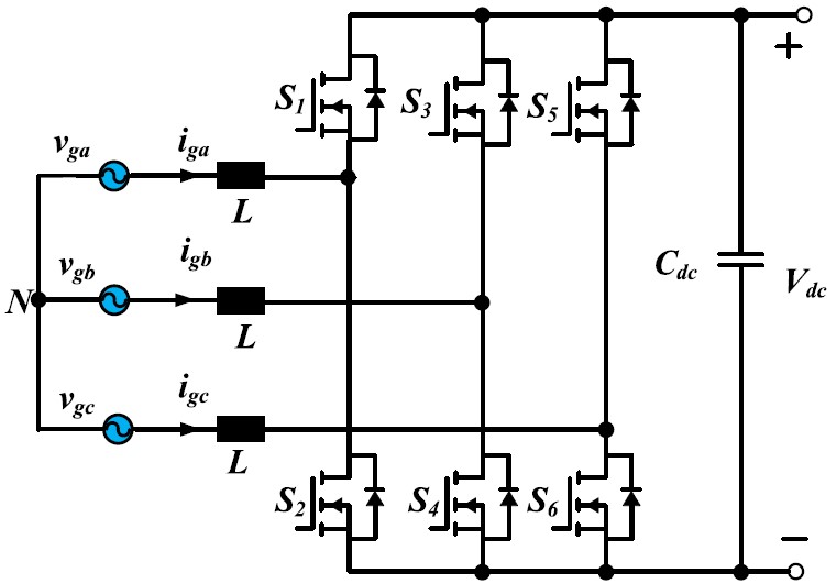
Figure 6. Three-phase six switch boost rectifier. Image used courtesy of M. Safayatullah et al.
Key Takeaways of AC-DC Converter Topologies in EV Fast Charging
This article discussed the various AC-DC converter topologies used in fast charging. Some of the takeaways follow.
- AC-DC converter is an essential component of an EV fast-charging station. These fast charging stations are usually outside the EV as offboard charges to reduce the size and weight of the EVs.
- The TPBR and Swiss rectifiers have high efficiency and offer low THD. However, conventional TPBR suffers from high voltage stress and reduced soft-switching capability.
- Swiss rectifiers are an improvement over the TPBR in terms of efficiency and noise rejection, but they are unidirectional and complex to control.
- The Vienna rectifier has a smaller number of switches, and they are compatible with the bipolar bus. They are free from neutral structures as well. However, they require DC link capacitors, which increases the cost and complexity of the system.
- The three-phase boost rectifier has a simple structure and lesser input current stress. They have the bidirectional capability with a continuous input current. However, the switching losses are higher due to antiparallel diodes in the semiconductor switches during reverse recovery.


