
As a fundamental tool to improve production efficiency, condition monitoring is accelerating the transition to Industry 4.0. It enables continuous monitoring of electromechanical equipment and power devices, facilitating early detection and real-time diagnosis of possible anomalies or failures. By identifying and isolating potential problems before they can compromise production, condition monitoring makes it possible to optimize the maintenance function and maximize equipment uptime by scheduling maintenance-related downtime periods efficiently.
Power devices such as electric motors, pumps, bearings, and encoders are subjected to electrical, mechanical, and environmental stresses that can negatively affect their operation. In addition to monitoring electrical parameters such as voltage and current, it is essential to perform vibration, noise, and temperature measurements to ensure equipment health. A modern condition-monitoring system typically comprises sensors of various types, usually installed directly on power devices; digital electronic circuits for collecting and sending data to the cloud; and an appropriate software application, available both on desktops and on mobile devices.
By accessing data on cloud servers, maintenance personnel can get a clear idea of the health of the devices and take corrective action to forestall problems. Condition monitoring therefore changes the maintenance approach from reactive to predictive, potentially lowering maintenance costs as it shortens downtime and increases production efficiency.
Condition-monitoring sensors
Sensors are deployed in condition-monitoring systems to send data to the cloud automatically, reliably, and without human intervention. To illustrate, let’s consider a classic example that’s common to most industrial production plants: rolling element–bearing failure that results from bearing wear and tear. Bearing wear occurs in virtually all types of rotating machinery, including motors, turbines, pumps, fans, and computer numerical control (CNC) machines. Typically, a high-frequency noise outside the audio band is the first symptom of a worn bearing.
Low-noise, high-resolution wideband vibration sensors are used to measure those frequencies, enabling early detection of bearing wear caused by the detachment of small metal fragments. Mathematical techniques such as envelope detection — usually combined with complete spectral analysis in the frequency domain — are deployed to detect, diagnose, and understand the implications of failures affecting the bearings.
Another important factor to monitor is imbalance, which in this context is an uneven distribution of mass that can cause the center of mass to move away from the center of rotation. Common causes include design error, faulty installation, component wear, and the presence of dirt or other contaminants.
For example, accumulation of dust or grease on a fan used for cooling motors or other power devices can unbalance the fan and cause a blade to break. Imbalance generates a signal with the same frequency of rotation as the system and amplitude proportional to the square of the frequency. Therefore, imbalance detection is performed through analysis in the frequency domain. Low-noise, wideband sensors are used for imbalance detection, focusing the analysis on the first-order harmonic components.
A third common problem is parallel or angular misalignment of the rotating shafts. Misalignment induces considerable mechanical stress, which can cause components to fail. The problem typically is detected by analyzing the second harmonic speed (i.e., 2× the fundamental frequency) of the system rotation speed.
Misalignment measurement is carried out using multiple accelerometer sensors capable of detecting the number of vibrations at different points on the equipment. In this way, it is possible to determine the phase difference between the measurements and thereby determine the type of misalignment (parallel, angular, or a combination of the two).
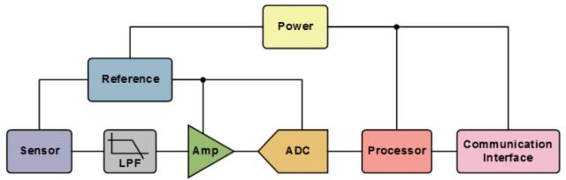
Figure 1 shows a typical condition-monitoring system. The data acquired by each sensor passes through a low-pass filter (LPF), which eliminates undesired frequency components; a low-noise amplifier; and an analog/digital converter. A digital system (microcontroller or microprocessor) processes information and transmits it to the remote cloud server via a wired or wireless network connection. Most of the sensors used for this application are now manufactured using microelectromechanical-system (MEMS) technology to provide extended measurement ranges and high reliability even in the most severe operating conditions.
Commercial-grade sensors
Analog Devices’ portfolio of MEMS inertial sensors includes accelerometers, gyroscopes, and inertial measurement units (IMUs) for addressing complex application needs. The company’s ADIS16228 is a highly integrated vibration-sensing system that combines triaxial acceleration sensing with advanced time- and frequency-domain signal processing. Time-domain signal processing includes a programmable decimation filter and selectable windowing function (rectangular, Hanning, or flat top).
Frequency-domain processing includes a 512-point, real-valued fast Fourier transform (FFT) for each axis, along with FFT averaging, which reduces the noise floor variation for finer resolution. The 14-record FFT storage system offers users the ability to track changes over time and capture FFTs with multiple decimation filter settings.
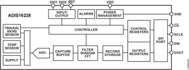
The device, whose functional block diagram is shown in Figure 2, provides a 20.48-kSps sample rate and 5-kHz flat frequency band, making it suitable for machine-health applications such as vibration analysis, condition monitoring, instrumentation, and diagnostics, according to the company.
Capacitive MEMS benefits
Traditional vibration-sensing instruments are based on piezoelectric technology, but capacitive MEMS technology is gaining popularity in this field for various reasons: The frequency response includes DC and has great stability over time and temperature; the digital output does not require external A/D conversion or signal-conditioning circuits; and the devices are robust, highly reliable, and small-footprint.
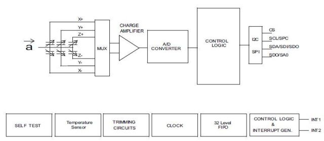
STMicroelectronics’ IIS2DH, for example, is an ultra-low–power, high-performance three-axis linear accelerometer with digital I2C/SPI serial-interface standard output (Figure 3). The MEMS accelerometer has user-selectable full scales of ±2 g/±4 g/±8 g/±16 g and can measure accelerations with output data rates from 1 Hz to 5.3 kHz.
The device may be configured to generate interrupt signals by two independent inertial wake-up/free-fall events as well as by the position of the device itself.
The IIS2DH can be configured in three operating modes (low power, normal, and high resolution), with power consumption down to 2 μA. Its integrated self-test capability lets users check the functionality of the sensor in the final application.
The IIS2DH is available in a small, thin, plastic land grid array (LGA) package and is guaranteed to operate over an extended temperature range from –40°C to 85°C.

