
A radio receiver is an electronic device that receives radio waves and converts the information carried by them to a usable form. To capture the required frequency waves, an antenna is utilized. The receiver employs electronic filters to isolate the necessary radio frequency signal from all other signals picked up by the antenna, an electronic amplifier to boost the signal's strength for further processing, and lastly demodulation to extract the desired information. In this project, the circuit diagram is taken as a reference and the connections are made accordingly to check the working of the radio receiver.
On the other hand, a radio receiver kit is a package that contains all the necessary components and instructions to build a radio receiver. The kit is meant for electronics enthusiasts, students, or hobbyists who wish to learn more about the workings of a radio receiver by assembling one themselves. The kit provides the parts and guidance needed to build the receiver. The radio receiver is the end product of assembling the kit.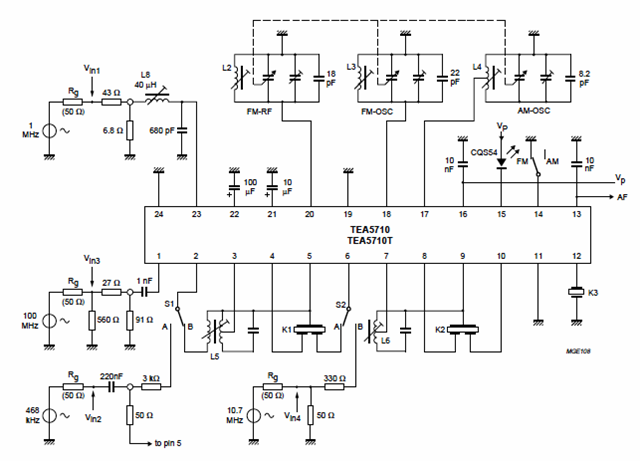
FM radio receiver block diagram
INTRODUCTION
A radio or FM recipient is an electronic gadget that gets radio waves and converts the data conveyed by them to a usable structure. The recipient utilizes electronic channels to isolate the ideal sign from the wide range of various signs got by the radio wire, an electronic speaker to build the force of the transmission for additional handling, and lastly recuperates the ideal data through demodulation. Of the radio waves, FM is the most famous one. Frequency modulation is generally utilized for FM radio telecom. It is additionally utilized in telemetry, radar, seismic prospecting, and checking babies for seizures through EEG, two-way radio correspondence frameworks, music unions, attractive copying frameworks, and some video-transmission frameworks. A benefit of recurrence balance is that it has a bigger signal-to-noise proportion and consequently dismisses radio recurrence obstruction better than an equivalent power amplitude modulation (AM) signal. The project helps to better understand the working principle of FM radio receivers along with practical experience while designing them. Moreover, familiarization with the tools like soldering and other small components helps better grasp the subject.
PROJECT OBJECTIVE
The aim of the project is to
- Help understand the working of FM receiver
- Circuit diagram build-up
- Make connections in soldering
- Recognize various applications of FM
- Familiarization with various components used
DESIGNING AND WORKING PRINCIPLE
An FM radio receiver IC (Integrated Circuit) is a type of microchip that is designed to receive frequency modulated (FM) signals. This IC is often used in portable devices like smartphones and radio players due to its small size.
These ICs have all the necessary components such as an RF amplifier, mixer, local oscillator , IF amplifier, and demodulator integrated into a single chip, which simplifies the design and construction of an FM radio.
The signal from the transmitter is an antenna, and the signal is then sent through a preselect filter, which separates the FM signal from the electromagnetic area, and the output signal is supplied to a mixer, which takes two distinct inputs, one from the amplifier and the other from the oscillator. We can tune our oscillator to change the output of our mixer so that we can select different stations. The output of the mixer is then sent to an Intermediate Frequency (IF)Filter that can filter the specific frequency that we require, that signal is sent to a demodulator which takes the important information and turns it back to audio. We can then amplify that audio using Audio Amplifier and get the output in the form of some Sound from speakers/headphones/buzzers etc.
The module is built around the HEX3653 IC, which is effectively an FM radio chip capable of receiving modulated FM transmissions with frequencies ranging from 76 to 108MHz. This module's inbuilt circuit allows you to adjust the volume, search stations on the FM band, and utilize an external antenna if necessary. The filters will distinguish between the targeted radio frequency signal and all other signals picked up by the antenna. The amplifier is used to increase the power of the signal for the demodulation process of the FM composite signal.
An FM radio receiver circuit is an electronic circuit designed to receive and demodulate FM (Frequency Modulation) radio signals. This circuit typically consists of several key components:
-
RF Amplifier: Amplifies the weak radio frequency (RF) signal received by the antenna.
-
Mixer and Local Oscillator: Converts the amplified RF signal to a fixed intermediate frequency (IF) signal.
-
IF Amplifier: Further amplifies the IF signal.
-
FM Demodulator: Extracts the original audio signal from the modulated IF signal.
-
Audio Amplifier: Amplifies the audio signal to a level suitable for driving a speaker or headphones.
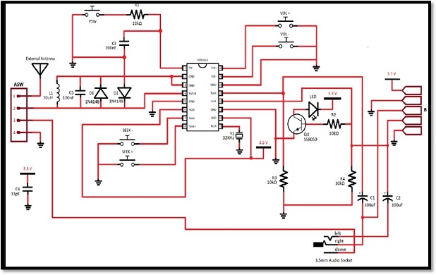
Circuit Diagram
How to make FM radio receiver ?
In order to assemble the components in the above circuit diagram, we need:
- Soldering Iron
- Tin-Lead Solder
- Flush Cutters
- Wire strippers
- 4 10K ohm Resistors
- 5 mini push buttons
- 2 100nF capacitors
- 1 NPN transistor
- 1 jumper
- 1 32KHz Round Crystal
- 1 3.5mm Stereo Audio Socket Phone
- 1 3mm yellow led
- 1 inductor
The circuit provides audio filters using capacitors and resistors (RC filters) to provide a clear and high-quality sound when receiving a strong FM signal. The antenna is selected via the ASW (Antenna Switch) header. As radio waves are intercepted by the antenna, electrons in the antenna begin to vibrate up and down. The antenna signal originates at the header pins. Pin 1 on the header is for the connection of an external antenna. Pin 2 is linked to the HEX3653 chip. Pin 3 is linked to the antenna shield of the 3.5mm audio socket, allowing the auxiliary cable to function as an antenna. The auxiliary cable is utilized as an antenna by connecting pins 2 and 3 using a jumper sleeve. Adding the jumper sleeve over pin 1 and pin 2 allows us to use an external antenna. The remaining fourth header pin is connected to the ground. Since our configuration has the jumper sleeve placement on pin 2 and pin 3, the auxiliary cord or headphone cord is acting as the antenna, so the antenna signal is being received at the headers from pin 3 and passed to pin 2.
The alternating current flows from the second pin of the ASW header through the 10H inductor (L1), the 33pF capacitor (C4), and the 1N4148 diodes (D1 & D2) to restrict the pin voltage to roughly 0.3V and safeguard the chip. This signal is received at pin 4 of the HEX3653 chip (FM IN). This incoming signal is then compared to the reference signal received from the onboard antenna which is a 32KHz crystal connected to pin 9 (RCLK). The SEEK and SEEK- push buttons control the RCLK signal. The tuning, detection, and amplification of the signal are all done inside the HEX chip. The audio output is at pins 12 (Lout) and 13 (Rout). Both signals are linked to 10K resistors (R2, R3, and R4) and DC blocking 100F electrolytic capacitors (C1 & C2) to prevent 0Hz frequency DC signals from flowing through and generating distortion. This RC network (resistor-capacitor) also serves as a high-pass filter, allowing only the audio signal to pass through while filtering out any unwanted noise.
RESULTS AND DISCUSSION
As soon as the power is supplied, the LED light glows up. This gives us an indication of the accurate functioning of the circuit. Moreover, when the seek button is pressed the FM starts to capture the signals and the audio can be heard on the speakers attached. Double pressing the SEEK button the channel is tuned to another frequency. Similarly, the VOL and VOL- buttons can be used to maximize and minimize the volume accordingly. The jumper is used to provide a better and clear sound, canceling the noise effect.
CONCLUSION
The FM radio build via the circuit diagram helped us better understand the functioning along with the usage of the HEX 3653 model chip. Soldering is the most critical part of this project as it is to be done with quite precision to avoid errors. This project sets a good baseline to learn the concepts of AM modulation along with hands-on experience in the practical formulation of the circuit with the help of a circuit diagram. Therefore, along with theoretical concepts, it is necessary to learn practical examples via similar projects.
REFERENCES
https://www.electronicsforu.com/electronics-projects/simple-fm-receiver

