
In the complicated world of automotive engineering, transmission speed sensors play an important role in making sure our vehicles work smoothly. It is the main component that does the monitoring speed over which gears of vehicles are rotating and transmits important signals to the engine control unit (ECU). The faulty speed sensor data can cause different problems such as erratic shifting to check the engine light.
What is a Transmission Speed Sensor?
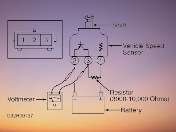
The transmission speed sensor is known as the vehicle speed sensor (VSS) or output shaft speed sensor . It is a small size component but considered important for drivetrain of vehicles. Its main function is monitoring the speed of different components in the transmission and sending this data to the ECU or transmission control module (TCM).![]()
figure 1 what is a transmission speed sensor
How Does It Work?
The working principle of transmission speed sensors is very simple. It normally has a magnetic coil and reluctor ring. The reluctor ring is configured on rotating components existing in transmission like the output shaft. When components rotate it pass through a magnetic coil to produce a small electrical signal. The frequency of the signal is based on the rotational speed of the component. The ECU or TCM explains this signal to measure the speed at which different gears of transmission are rotating
How to Test Transmission Speed Sensor
Tools and Materials You Will Need
Tools:
- Jack stands
- Jack
- Multimeter
- Safety goggles
- Gloves
Materials:
- Service manual for vehicle
- Pen and notepad
Step-by-Step Guide to Testing Your Transmission Speed Sensor
Step 1: Safety First
There must be a priority given to safety when you are working on the vehicle. Must park the car on a level surface, engage the parking brake, and use safety goggles and gloves during the process to protect yourself from potential hazards
Step 2: Disconnect the Sensor
Disconnect the electrical connector connected to the speed sensor carefully. Try to avoid the wires damaging or the sensor itself. Check carefully that there is no sign of corrosion or visible damage.
Step 3: Test with a Multimeter
- Set the multimeter to ohms or resistance setting. it will help us measure the electrical resistance of the sensor
- Setting the multimeter connect probes with terminals on the sensor. There are 2 main terminals on the sensor.
- The range of resistance values listed in the vehicle's service manual must be fulfilled by a working speed sensor. For the accurate resistance value that your sensor must display, consult the handbook.
- If the resistance reading value does not lie in that specified range, It is a sign of some issue with the sensor. So we must think about getting the services of a mechanic for further details and potential replacement.
Step 4: Inspect the Wiring
During the sensor testing also check the wiring that is leading to it. Find if there is any sign of damage, fraying, wear, or exposed conductors. If you check if there is any issue with the wiring there is a need to be replaced or repaired to ensure the accurate function of the sensor
Step 5: Clear Error Codes
If the vehicle is showing a check engine light due to a faulty speed sensor , there can be an OBD-II scanner used to clear the error codes after finishing the test. This step is important for resetting the vehicle's computer system and making sure proper monitoring.
Step 6: Reconnect the Sensor
When you are done testing the sensor and addressing any wiring problems, reconnect the electrical connector to the speed sensor. Check that it is properly fastened to avoid any future issues.
Step 7: Lower Your Vehicle
Using the jack carefully remove the car from the jack support. Before continuing, ensure that the car is properly parked and is steady.
Step 8: Test Drive
At last, take your vehicle for a test drive to check its performance. Check the behaviour of transmission like shifting smoothness and absence of warning lights. An accurate functioning sensor must result in improved transmission performance.
Symptoms of Faulty Transmission Speed Sensor
The Symptoms of Faulty Transmission Speed Sensor are explained here
- Erratic Shifting:The most common symptom is erratic or unpredictable shifting behavior. We can face abrupt or delayed gear changes that can affect driving and have the risk of being potentially unsafe.
- Check Engine Light:A faulty speed sensor can trigger the check engine light existing on the dashboard of the vehicle. Currently used vehicles come with onboard diagnostics (OBD) systems that can easily detect irregularities in sensor readings and blink the check engine light as a warning sign.
- Inaccurate Speedometer:The speedometer is based on data from the speed sensor to show the speed of the car accurately. The faulty sensor can result in the speedometer providing an errored reading that can cause speeding tickets or difficulties in maintaining regular speed
- Loss of Cruise Control:Different vehicles use data from speed sensors for cruise control functions. If the sensor not working then cruise control becomes unavailable or behaves erratically.
- Stalling or Poor Acceleration: A faulty speed sensor can prevent the gearbox from varying gears when it should. As a result, the vehicle can stall when slowing down or accelerate slowly when it trying to gain speed.
- Harsh Downshifting:In some conditions, a malfunctioning sensor can cause the transmission to downshift suddenly when it shouldn't, it upraptly decreases speed and potential loss of control.
- Increased Fuel Consumption: A malfunctioning speed sensor can cause ineffective shifting that increases fuel consumption since the engine has a harder time getting the proper gear, especially while traveling in cities.

