
Overview: This article describes transverse flux permanent magnet machines, their design, classification, and applications. It discusses its advantages in direct-drive wind-generating applications and presents various surface-mounted machine topologies.
The permanent magnet machines are not ready-made machines. Their design is very flexible, so they can be used in a lot of different ways and more widely in wind-turbine applications, promoting the development of renewable energy. They are usually classified based on the direction of the flux as radial flux, axial flux, and transverse flux.
Transverse flux permanent magnet (TFPM) machines are a viable option for direct-drive wind-generating applications. They have high torque and power densities.
How can transverse flux permanent magnet machines be classified?
There are two types of TFPM machines:
- Surface-mounted TFPM machines
- Flux concentrated TFPM machines
The TFPM machines can be divided into the following groups according to their electromagnetic configuration:
- Single-sided and double-sided
- Single winding and dual winding
- Inner rotor and outer rotor
- Stator type: C/U-core, Z-core, E-core, claw pole
A number of surface mounted TFPM machine topologies are presented and examined in this article.
Surface-Mounted
The TFPM machine's surface magnet shape exhibits permeability similar to that of a non-salient synchronous machine in which the PM and air gap are both present.
The opposing cogging torque and the interaction torque component make up the overall torque. Also, the surface magnet TFPM machine has a bigger active air gap because the magnets create an extra air gap.
Single-Sided
Fig. 1 illustrates the basic topology, which consists of a rotor core with magnets bonded to its surface. The winding is positioned in the laminated steel iron core with a C/U shape.
Fig. 1. Single-sided surface-mounted TFPM machine Source: IEEE Access
An alternating flux is created in the stator as a result of the magnets with alternating polarity being displaced on the rotor. Every pair of poles generates a flux that is connected to the same global winding.
Challenges
Just half of the magnets in this topology are in use at any given time, while the remaining magnets generate flux that can reduce the flux associated with the winding. It also has a strong reaction to leaks.
Additionally, a two-phase TFPM machine was suggested. In comparison to a standard induction machine, the torque density of this machine is five times higher. This was an even more optimized machine. However, high flux leakage between the stator and rotor was demonstrated. In addition, the machine experiences opposing fringing fluxes with a decreased back-EMF.
A TFPM machine with an external rotor was created. With inadequate thermal management pathways for heat disposal, the outer rotor design has a high torque density.
Moreover, a surface-mounted TFPM machine with intermediate poles achieves greater performance with complete magnet utilization. At the same volume, the output of this topology is twice as high as that of the traditional TFPM machine. Unfortunately, this machine is less efficient and has substantial losses and 3-D leakage.
Iron Bridge
As shown in Fig. 2, guiding iron bridges could be positioned between the stator cores to reduce the stray flux generated by inactive magnets. In this way, the magnetic flux from each magnet will have a closed path that doesn't affect the growth of the main magnetic flux. This setup would probably result in higher output power.
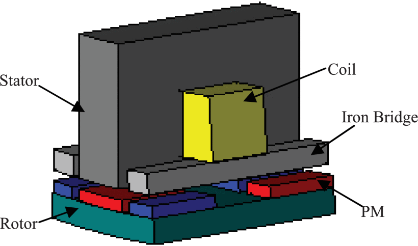
Fig. 2. Single-sided TFPM machine with iron bridge Source: IEEE Access
Challenges
Nevertheless, the machine will get heavier due to the iron bridge, the reduced area of the stator winding, and increased core losses. The bridges will also cause a significant leakage flux from the nearby stator cores.
An iron-bridge TFPM machine design that is distinct from others is being examined. The rotor resembles a hybrid stepping motor with a PM ring that is axially magnetic. The machine's high PM usage causes it to have a high cogging torque.
An outer rotor generator with an iron bridge, based on the TFPM machine principle, was proposed. The 6 KW generator has a power factor of 0.58 and an efficiency of 92%. This design's primary flaw is the stator core's excessive flux leakage.
A semi-open slot is inserted in place of an open slot to optimize the same topology. As a result of the eddy current in the iron bridge, the machine has a high power factor of 0.8 and high power losses.
A fallback generator is suggested as a way to reduce the magnet volume. The fundamental design is comparable to that of a traditional TFPM machine with an iron bridge. But in this topology, only half of the magnets are utilized.
To fulfill the objective of inactive magnets, the inactive magnets are removed, and the magnetic flux is redirected through a rotor from the return direction (fall-back path). In terms of magnet use, the iron bridges are superior by 84%.
Because it makes greater use of magnets, this design is also being extensively researched for wind power applications.
Double-Sided
An alternate design for the machine that makes use of all the magnets is to use two stators, one on each side of the rotor, as shown in Fig. 3. Each pole pair in this topology has two sets of C/U-shaped cores, with the winding positioned in the slots.
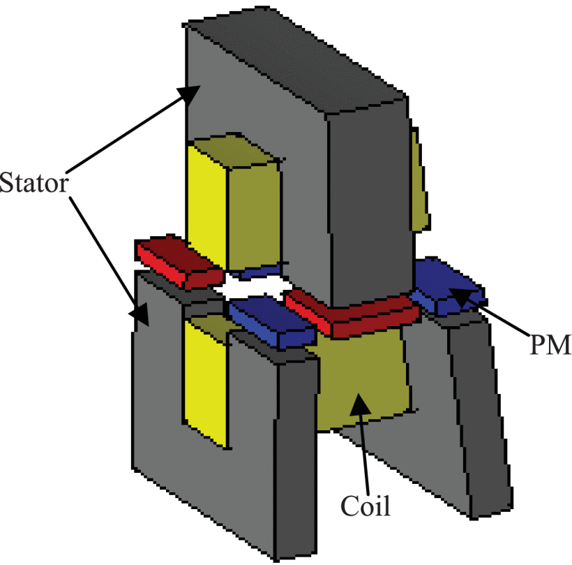
Fig. 3. Double-sided TFPM machine with iron bridge Source: IEEE Access
The rotor cores contain the magnets incorporated in them. When compared to a single-sided design, the machine performs two times better. In this topology, iron bridges can be built to give the magnetic flux a return path.
In comparison to a single-sided TFPM machine, the double-sided surface-mounted TFPM machine has a greater volt-ampere rating for the same volume and relative pole pitch.
Challenges
The disadvantage, though, is that building the active rotor components is more difficult because they must be supported in a cantilevered configuration.
With almost the same torque production as in the double-sided TFPM machine with two windings, this architecture can also be built with just one winding. Its shorter outer diameter and straightforward mechanical structure are advantages.
Furthermore, for wind turbine generators, a double-sided modular TFPM machine with an axial flux design has been developed. Nevertheless, the structure of this topology is complex due to leaking at the rotor pole.
Claw Pole
Another strategy is to twist the stator core so that, as shown in Fig. 4, all of the magnets can be utilized at the same time. A claw pole is the term for this kind of configuration. Only half of the stator tooth faces the pole region at any given moment, as can be seen in the illustration.
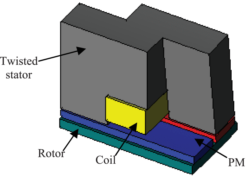
Fig. 4. Single-sided surface-mounted claw pole TFPM machine Source: IEEE Access
By doing this, the armature flux leakage between the twisted stator teeth is reduced.
Challenges
With low magnetic flux linkage, the shorter tooth span will result in saturation at the stator tip. The intricate complexity of this machine also makes it mechanically unstable.
Various claw pole shapes have been studied in an effort to improve power factor and achieve high torque density. The axially reduced claws prevent inter-polar flux leakage in the armature.
For improved magnet utilization, a single-sided claw-pole TFPM machine was suggested. The material used to create the claw structure is called soft magnetic composite, or SMC. The finite element method (FEM) and analysis are used to optimize the machine.
A recently proposed single-sided TFPM machine has an outer rotor and a non-overlapping stator pole. With this new architecture, winding and magnet usage are 100% while the conductor space is not reduced.
Summarizing the Key Points
- Transverse flux permanent magnet machines are a viable option for direct-drive wind-generating applications due to their high torque and power densities.
- TFPM machines can be classified into surface-mounted and flux concentrated types and further divided based on their electromagnetic configuration.
- Challenges associated with TFPM machines include low magnetic flux linkage, saturation at the stator tip, and mechanical instability.
- The design of permanent magnet machines is highly flexible, allowing for their use in a variety of different applications.
- TFPM machines have the potential to revolutionize the field of wind power generation and offer a promising alternative to traditional direct-drive generators.
Reference
Kumar, Rajesh, Zi-Qiang Zhu, Alexander Duke, Arwyn Thomas, Richard Clark, Ziad Azar, and Zhan-Yuan Wu. “A Review on Transverse Flux Permanent Magnet Machines for Wind Power Applications.” IEEE Access 8 (2020): 216543–65. https://doi.org/10.1109/access.2020.3041217.


