
We all know the phenomenon of connecting two wires, in which we strip the insulation of the wire at the ends and twist them together. This seems easy but not a safe way at the same time. Here comes the terminal blocks or terminal block connectors to solve this problem. With these electric terminal blocks, we not only connect multiple wires near each other and with a single incoming wire but also a safe way to join wires together. So what is a terminal block or terminal block connector? A terminal block also known as a terminal connector or connection terminal is a modular type block structure that sources two or more wires together with an insulated frame. It has a conducting strip joined with clamping components.
Connection method:
A typical method of connecting is with a use of a screw in which wires are inserted in the block connector and then we clamped the wires with a single screw. On the other hand, larger terminal blocks with larger cables have a screw pushing the wires against a metal body. In the case of thin wires, a lever or a flat head is pushed down by a screw that compresses the wire against a metal insert. Some types of terminal blocks may have screw less levers, that work like a fish trap. In this, the wire is inserted and the level comes down to hold the wire and prevent it from being pulled back out. In some other types, screws are used for holding the inserted cable at one end and a plug on the other end that later can be inserted into a female socket.
Here is a simple video that shows the method of connecting wires with a typical terminal block connector,
How to connect wires with a terminal block
Types of terminal blocks:
Let's discuss different types of terminal blocks based on their Structure, device, and clamping options.
a). Single-level terminal blocks:
These are simple terminal blocks and are used to connect two wires, simply use these connectors for wire-to-wire connection. This type of connector has only one input contact and one output contact.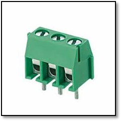
Figure 2 A single level terminal block
b). Dual-level terminal blocks:
In dual-level terminal blocks, we have another block level of connection terminal on the first block of the terminal which saves the space and provides the dual connection.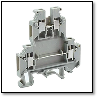
Figure 3 Dual level Terminal Block
c). Three-level terminal blocks
Their structure is the same as dual-level blocks with three levels of terminals of blocks on each other. These type of terminal blocks allow us to have multiple connections on the same terminal block connectors.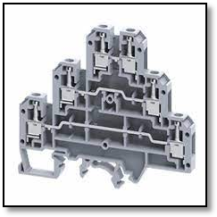
Figure 4 Three level terminal block
Device type:
These are just like single-level feed-through terminals. The only difference between them is the grounding of the metal connection with the panel. The metal connections are the components where the wires will be connected.
Figure 5 A ground terminal block
b). Fused connection terminals:
These connection terminal blocks work the same as pass-through blocks where we use a fuse instead of a connection metal strip.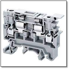
Figure 6 A fuse terminal block
c). Thermocouple Terminal Blocks:
These terminal blocks are equipped with thermocouple lead connections. These thermocouple connectors clamp the leads at the input and output end of the block. Usually, these block connectors are not equipped with the metal connection strip, but in some cases same type of metal strip is present in the block as of connecting wire.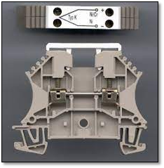
Figure 7 Thermocouple terminal block
c). Power distribution blocks:
In electrical power distribution, the power distribution blocks are widely used. Distribution terminal blocks are a convenient and safe way to distribute electricity from a single input source to multiple outputs. A main larger incomer wire is connected at the input terminal that divides the electricity into multiple output sources at the output side of the power distribution block.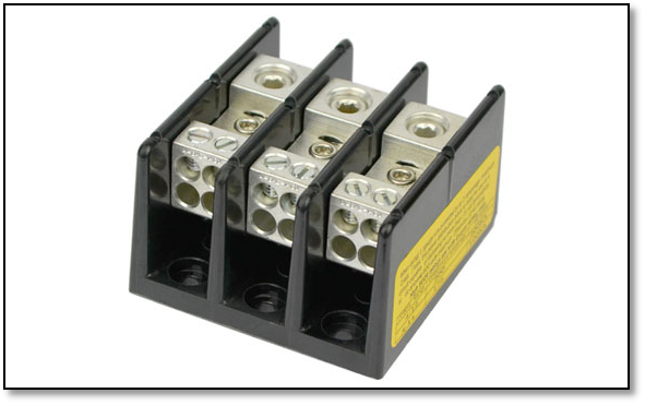
Figure 8 Power distribution terminal block
Types on the base of clamping
a). Screw type terminal block:
This is the most common type of terminal block for connection methods. We simply pass the wire through the conducting strip and hold the wire by tightening the crew of the terminal block. These terminal blocks can be used with a wide range of wire sizes.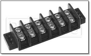
Figure 9 Screw type terminal block
b). Spring Clamp:
As the name shows a spring pressure is used to hold the wire. These are suitable for smaller wire sizes.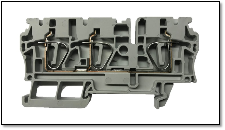
Figure 10 Spring clamp type terminal block connector
c).Push in terminal blocks
With the push-in terminal blocks, we can connect the wires by simply inserting wire in it. A ferrule is required in most of the push in terminal blocks.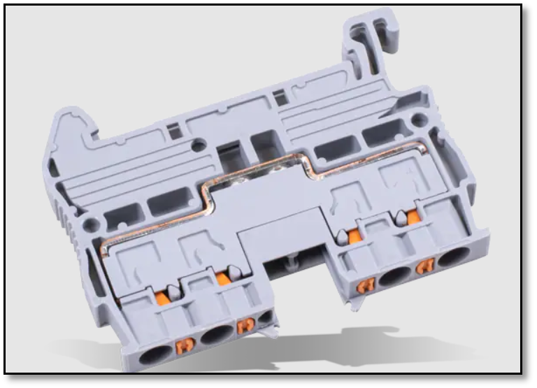
Figure 11 A push in terminal block
Selecting the right terminal block connector
Choosing the suitable type of terminal block involves factors like current, voltage, conductor size, and the surrounding environment. Selection based on these factors seems easy but it's a complex procedure. Let us discuss this in detail.
Current
The flow of very large current through a terminal block causes overheating and exceeding the value of current from the rated value can destroy the terminal block so the current value is the most important aspect of choosing a terminal block.
Voltage
Similarly, the voltage should not be greater than the rated value and must be taken into account. Because too high a voltage can cause current leakage between terminal blocks
Conductor Size
Wire size is also an important factor when choosing the right terminal block. A terminal block must hold and tight the wire appropriately to avoid faults in terminal blocks
Environmental factors:
Different environments have different effects on the performance of the terminal blocks. we use terminal blocks at places with high temperatures as well as low-temperature areas, moisture and salty air affect the terminal block, that damages the terminal blocks.

