
Logic probes are very cheap and easy to use as simple digital testers in many applications. Logic probes can provide a simple way of testing slow moving digital logic levels and signals.
Being very cheap to buy, these digital logic probes are ideal for experimenters, but they will seldom be found in a professional electronics laboratory because of their limited measurement capability and the availability of more advanced test equipment, like logic probes or mixed signal oscilloscopes or other forms of electronic test equipment.
What is a logic probe?
The logic probe or digital tester is normally a low cost handheld probe contained within a pen-like tube with indicator lights to show the state of the line being probed.
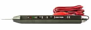
Typically logic probes are used to test digital circuits like those using TTL or CMOS logic. They often have three indicator lights on the body to indicate the state of the line. As such logic probes are very basic forms of digital testers, only able to test the state of a single line, but they can be useful in many applications.
The logic probe is normally powered by the circuit under test - there are normally leads with crocodile / alligator clips that can be attached to the ground and supply of the circuit under test.
Logic probe measurements
A logic probe is restricted in the number of measurements it can make when compared to other test instruments, but it can nevertheless be used for a variety of digital measurements:
- Logic high state: The logic probe / digital logic tester is able to detect lines that are at the digital or logic high state. The logic probe will indicate this typically with an LED which is often coloured red.
- Logic low: The logic probe also is able to indicate a logic or digital low. A common indication is with the use of a green coloured LED.
- Digital pulses: The logic probe may incorporate some form of pulse detection circuitry. When the line is active and being pulsed a third colour, possibly amber will be indicated. The logic probe may well incorporate circuitry to detect very short pulses and in this way indicate when the line is active. Sometimes the length of the pulses may be indicated by the brightness of the LED.
- Line tri-stated: Some logic probes may also be able to detect when a line has been put into a tristate option. This is when the output device has its output turned off and no real logical state is defined. Many logic probes are able to indicate this state and they may do this by having all indicators turned off.
Logic probes vary from one manufacturer the next and therefore it is necessary to check exactly what measurements can be made and how the results are indicated.
Advantages and disadvantages of a logic probe
As with any item of test equipment, there are advantages and disadvantages to the use of a logic probe tester than need to be considered before buying or using one.
Logic probe advantages -
- Low cost: A logic probe does not contain much circuitry, and the display is very rudimentary. Therefore the cost of manufacture is very low – they can typically be bought for less than the cost of a very basic multimeter. Logic analyzers and mixed signal oscilloscopes cost very many times more than logic probes.
- Ease of use : To use a logic probe typically requires the connection of power leads and then connecting the probe to the required point on the circuit.
Logic probe disadvantages -
- Very rough measurement: The nature of the logic probe means that only an indication of the presence of a logic signal can be detected. It is not replacement for a test instrument such as an oscilloscope.
- Poor display: A logic probe only uses a few LEDs to indicate the nature of the logic signal. As a result, little information can be displayed about the nature of the logic signal that is detected.
A logic probe tester is a very cheap and simple item of test equipment. It is able to provide a quick but very basic test for many logic circuits. However it is not nearly as flexible as an oscilloscope or a logic analyzer.
A logic probe can be used for quick testing, whereas for more in-depth testing more sophisticated test equipment is needed. It should be remembered that it is not suitable for many high speed logic circuits. It typically will only be useful for basic tests on basic circuits.
Logic probe typical specifications
While all models of logic probe will vary slightly, it is possible to provide some outline of the typical specifications for a probe.
Generally logic probes are aimed at a basic test only and therefore offer a relatively basic level of performance. Nevertheless they can be invaluable in locating faults in many situations.
A typical specification may be:
| TYPICAL LOGIC PROBE SPECIFICATIONS | |
|---|---|
| PARAMETER | SPECIFICATION |
| Logic 1 Signal input level |
TTL: > 2.3V ±0.02V CMOS: > 70% Vcc ± 10% |
| Logic 0 Signal input level |
TTL: < 0.08V ±0.02V CMOS: < 30% Vcc ± 10% |
| Max supply voltage withstand | 20 V |
| Power supply range | 5 - 15 V |
| Signal input impedance | 1 MΩ |
| Max input signal frequency | 20 MHz |
| Minimum detectable pulse width | 30 ns |
The specifications will vary from one logic probe tester to the next, but they give the rough ideal of the performance that might be expected.
The logic probe can be a very useful simple tester and save the cost of more expensive forms of electronic test equipment having to be bought. If thier limitations are understood, then they can prove to be very useful in many instances with simple electronic circuits.

