
The choice of location for a WiFi router in the home, office or even a larger area such as a shopping centre, etc. can make a major difference to the coverage and overall performance.
In the home, changing the location of a Wi-Fi, IEEE 802.11 router can significantly improve its performance, allowing much faster download speeds and better connectivity to be provided where it is needed.
Factors affecting Wi-Fi propagation & coverage
There are many factors that come to play when looking at IEEE 802.11 Wi-Fi propagation and coverage.
The environment in which routers are located is often far from ideal. The Wi-Fi signals suffer from the interaction with many objects that are within the environment and are form part of the construction: walls, structural elements, furniture, windows, ornaments, . . . in fact anything which is within the environment will have some form of effect.
As the home or office environment is so full of objects and structures propagation for Wi-Fi signals is notoriously difficult to predict. They are affected in a number of ways:
- Free space path loss
- Reflection
- Absorption
- Diffraction
- Refraction
Wi-Fi propagation: path loss
Like all radio signals, Wi-Fi propagation is subject to the same laws of physics including those of path loss. The Wi-Fi coverage will be limited to some extent by the distance alone, although many other factors come in to play.
Under normal free space conditions the signal level is inversely proportional to the square of the distance from the transmitter.
Wi-Fi propagation: reflection
With many objects appearing in the signal path in the home, office or commercial / industrial environment, signals will be reflected by many surfaces and this will have an impact on the Wi-Fi coverage. Everything from walls to metal objects like desks, domestic appliances, etc . .
These reflections give rise to multiple paths for the signal. Using an antenna technology known as MIMO (Multiple Input Multiple Output), Wi-Fi is now able to make use of these multiple paths to send data at a faster rate. However in the past, it would result in interference and reduction in data rates.
Wi-Fi propagation: absorption
Absorption is another key issue for Wi-Fi propagation. In any environment where a Wi-Fi router is located, signals will need to pass through walls, floors and they will encounter many other objects.
These objects act like a barrier to the wireless signals. Considering the close analogy of light signals, they may be a complete barrier like a door through which it is not possible to see, opaque glass where the level of light is reduced, or clear glass though which very little light is lost.

The type of medium through which the Wi-Fi signal passes will affect the level of attenuation.
It is not possible to give exact figures for the different media, as specifications, thickness and many other factors determine the overall level of attenuation. However a table of many common substances will give a guide to the likely affect.
| RELATIVE ABSORPTION OF VARIOUS MATERIALS | ||
|---|---|---|
| MATERIAL | RELATIVE SIGNAL ABSORPTION | EXAMPLES OF USE OF MATERIAL |
| Air | None | Free space outside, etc . . . |
| Wood | Low | Wooden furniture, doors, wooden partitioning. |
| Plastic | Low | Some partitioning, many plastic items |
| Glass | Low | Plain windows, glass used in partitions |
| Tinted glass | Medium | Tinted windows |
| Water | Medium | Water tanks, acquariums |
| Plaster | Medium | Partitioning, walls, plasterboard walls |
| Bricks | Medium to high | Brick walls |
| Ceramic | High | Tiles |
| Concrete | High | Concrete floors, pillars |
| Metal | High | Metal structures |
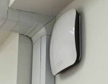
Locating router for optimum Wi-Fi coverage
One of the key ways of optimising your wi-fi coverage to locate the router in the best position.
Although it is not always possible to make major changes to the location of a router, it is often possible to make a different even by some small changes.
Often routers need to be located near a power point, and also close to the point where the DSL or fibre data line comes into the house, office or commercial / industrial premises.
When looking at the Wi-Fi propagation and coverage in any premises, it is first worth looking at where the Wi-Fi coverage is actually needed. In this way, the location of the router can be optimised to ensure that a good signal is present in the places where it is needed.
A few simple rules can help optimise the Wi-Fi coverage and signal propagation.
- Ensure signal does not pass through thick walls: Dense walls, especially those using concrete will significantly reduce the signal. For optimum Wi-Fi propagation and coverage, make sure the signal does not need to pass through thick walls to reach any high usage areas.
- Locate router above desk height: Most phones, laptops and tablets using a local Wi-Fi signal will be located above desk height and to gain the optimum signal path with the minimum of obstacles, it is best to locate the router above the desk height. Desks and other furniture will attenuate any signal, as will the wires and other metalwork associated with them.
- Don’t locate the router next to many other wires: Although locating a router, for example, in a cupboard next to the fuse box etc. may be convenient, the wiring is likely to shield the signal from many areas.
- Keep router as close to main areas as possible: The Wi-Fi coverage and signal propagation will benefit from being as close to the main areas of use as possible. Path loss from the distance the signal travels will be minimised and in addition to this the signal will need to travel through fewer obstacles.
Wi-Fi coverage planning tools
When planning Wi-Fi coverage for a major area like a shopping mall or conference centre, a more rigorous approach is needed. Software planning tools are used along with a comprehensive site survey using the plans for the area.
These tools look at the Wi-Fi propagation characteristics and then calculate Wi-Fi coverage.
These tools are not normally viable or accessible for domestic installations and small offices. It is for these instances where the guidelines above some in useful.
Even when automated software tools are used, some practical input helps feed in the relevant data correctly and then adds value to the output from them.
Other issues governing Wi-Fi coverage
Other factors also help Wi-Fi coverage and router performance. Some of these may need to be found by experimentation.
- Locate router away from interference: Locate equipment away from sources of possible interference. Obviously items like televisions that may be streaming data from a router will need to be able to receive a strong interference free signal. However the router also needs to be away from interference because it also receives management data from the remote equipment. If this suffers interference then data rates will be reduced. Sources of interference in the home are widespread. Microwave ovens transmit in the 2.4 GHz band and will cause interference, but other items like motors, fans, vacuum cleaners, fluorescent lights and many more create interference.
- Band selection: Wi-Fi is currently supported in both the 2.4GHz and 5 GHz ISM bands. 2.4 GHz will provide better coverage as signals in this band will penetrate walls and floors, etc. better. But against this 5 GHz offers a wider bandwidth and will be able to achieve a higher throughput under ideal conditions.

By optimising the location of the router, it will be possible to improve the Wi-Fi coverage and this will result in improved speeds in the areas where it is needed and also coverage in more areas of the premises, whether they are a domestic residence, office or other premises.

