
Smartphones and home appliances are amongst the applications that have evolved in recent years. One of the significant challenges is to optimize energy consumption as more and more devices enter the market. With IoT, connectivity becomes increasingly important as it allows maintaining proper communication and, as a result, standby consumption is turning into a real challenge. During APEC, Power Integrations announced LinkSwitch-TNZ, a new switching power supply IC family that reduces standby consumption in smart home applications and appliances to solve some of these challenges. In an interview with Power Electronics News, Adnaan Lokhandwala – Senior Product Marketing Manager at Power Integrations, pointed out that today, many devices operate in standby mode and, to meet various regulatory requirements, new solutions combining offline power conversion, lossless zero-cross detection and, optionally, X-capacitor discharge functions are required.
“Typical smart home products include switches and various plugs that remain continuously connected to the line. And, of course, they are also constantly communicating with smartphones. So standby power consumption is one of the key challenges with these products. Studies show that a number of devices are constantly waiting for power, accounting for 10% of household energy use, and 80 to 90% of the time they are in standby mode during the day without performing any function. For example, smoke detectors have to be connected to the AC line by regulation, but the duty cycle for that smoke detector is shallow. Smart appliances also have to meet certain regional regulations in terms of energy consumption, including standby consumption. So, for example, Europe has the EC 1275, which limits the maximum consumption for appliances sold in Europe to 500 milliwatts when they are switched off or are in standby mode,” says Lokhandwala.

Switching Solutions
We need to be aware of the limitations of standby, and reduction in losses to increase efficiency should be the mantra for any new design process.Two key functions very commonly used in these Smart home and appliance applications are the discrete AC zero crossing circuit and x-capacitor discharge. “AC-zero crossing is used in several applications to efficiently control the power going to the loads such as LED lamps. Unfortunately, the approach that’s used today is very lossy; it’s a very standard discrete circuit. The other function is to meet the safety requirements with a lot of these appliances. And today, that function is primarily done by using resistors across those capacitors (bleed resistors). Now, when you’re talking about full load, these two functions may not be very significant in terms of losses. But when you talk about standby, this can become a significant factor for the standby power budget that engineers have when they are designing these products,” said Lokhandwala.
LinkSwitch-TNZ aims to add the ability to combine a lossless zero crossing signal and x-capacitor discharge with the same switcher. “The implementation is a very simple non isolated back converter. The beauty of this approach is that you can derive the main output voltages needed, with a non isolated approach. Many of the applications today – even in smart homes – do not require an isolated power supply, because there is no direct human contact, and the isolation is actually coming from the casing. So, if you think about smart wall switches, they don’t require the power supply to be isolated. Of course this allows you to also avoid using custom transformers,” says Lokhandwala.
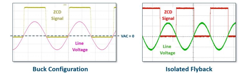
Devices such as switches, dimmers, sensors and plugs connect and disconnect the AC line periodically using a relay or TRIAC. “One of the challenges when you are connecting a relay is the correct synchronisation in switching on and off – the transition in all of this is very important. And then, of course, having the relay driver to provide the correct power,” says Lokhandwala.
A discrete circuit is typically employed to detect the zero-crossing point of the AC line to control the power-on transition of the main power device to reduce switching losses and inrush current. The BOM of this approach is decidedly uneconomical.
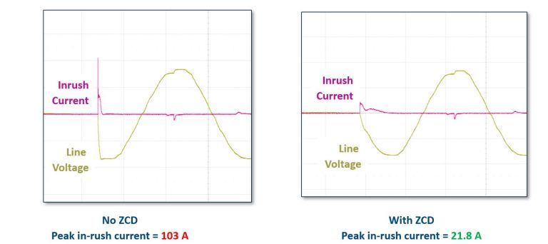
“What happens is that, at the moment of switching on the relay, there is a large inrush current which can be very high. The same is true in the switch-off process, and both cases can have an impact in terms of relay life -and of course, in this case, the life of the product as well,” says Lokhandwala.
Power Integrations claims that by integrating the zero-cross AC leakage detection on chip, LinkSwitch-TNZ ICs provide excellent light-load efficiencies, allowing multiple system functions to be powered while still meeting stringent standby regulations, such as the European Commission (EC) standard for household appliances (1275) that requires equipment to consume no more than 0. 5W in standby or off mode. Optionally, an X-capacitor discharge function can also be included in the package for high power applications.
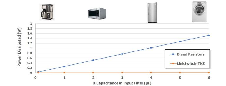
“Typically, the x-capacitor is used for higher power designs. an x-capacitor is typically a filter capacitor which is connected directly across the AC line for EMI reasons and RFI, minimizing that noise. So, as the power level goes higher, those x capacitors get larger and the impact of bleeder resistors is much higher. Typically,the capacitor discharge function is more relevant in appliances,” says Lokhandwala.
The block diagram in figure 3 shows a traditional mechanical switch in houses, which is now being replaced by more intelligent devices. It has a wire connected to the input and output…basically, there is no neutral wire connected to the system.
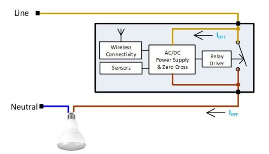
” Historically that hasn’t been a problem with mechanical switches because you don’t need a neutral wire, as they don’t have electronics. But now, when you make these smart products, you’re putting functionality inside, which means you need a constant source of energy to power these electronic devices. So, in a typical smart device, you would have a relay driver, an AC DC power supply, and a zero-crossing, discrete circuitry commonly used to ensure that the delay turns on at the right time. And you would have wireless connectivity and some sensors. Ioff is the leakage current when the load is off, as the relays use the other current path in the hope of conducting while on standby. To make sure that this current is kept extremely low, you have to optimize the system so that this off current stays low; if the current is high, the result is that the LED bulb, for example, comes on. This current can come and charge the input capacitor. And, as a result, it will basically turn the lamp on and off, which is something you don’t want. This effect is called LED ‘flickering’ or ghosting. So with the new product, we can eliminate the need for a neutral wire. And this is very common with homes and retrofit applications because, again, most homes in North America and Europe and Asia have never really been wired with a neutral wire. So, now you have to design a smart system that can work with the two wires or without a neutral wire. And what we did was to create a complete reference design, which in this case is a reference design for an intelligent dimmer switch based on Nordic’s BLE module,” said

