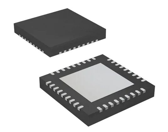
IC REG CTRLR BUCK 36QFN
The TPS40140RHHT is a multi-functional synchronous buck controller. This post will cover its datasheet, pinout, circuit, application, feature and more details about TPS40140RHHT.
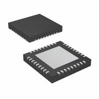
IC REG CTRLR BUCK 36QFN
The TPS40140RHHT is a multi-functional synchronous buck controller. This post will cover its datasheet, pinout, circuit, application, feature and more details about TPS40140RHHT.
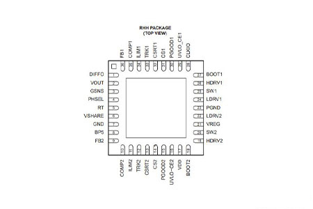
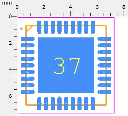
TPS40140RHHT Pinout
Symbol
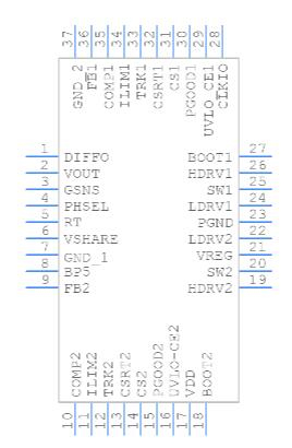
TPS40140RHHT Symbol
Footprint
TPS40140RHHT Footprint
3D Model
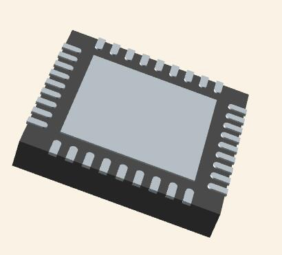
TPS40140RHHT 3D Model
The TPS40140RHHT is a multi-functional synchronous buck controller that can be configured to provide either a single-output two-phase power supply or a power supply that supports two independent outputs. Several TPS40140RHHT controllers can be stacked up to a 16-phase multi-phase single output power supply. Alternatively, several controllers providing multiple independent outputs can be synchronized in an interleaving pattern for improved input ripple current.
The TPS40140RHHT is capable of converting from a 15-V input to a 0.7-V output at 1MHz.
●VDD From 4.5 V to 15 V, With Internal 5-V Regulator
●VourFrom0.7Vto5.8V
●Converts From 15-V Input to 0.7-V Output at 1 MHz
●Dual-Output or 2-Phase Interleaved Operation, Stackable to 16 Phases
●Supports Pre-Biased Outputs Programmable Switching Frequency Up to 1 MHz/Phase
●0.5% Internally Trimmed 0.7-V Reference
●10-μA Shutdown Current
●Current Mode Control with Forced Current Sharing (1)
●1-V to 40-V Power Stage Operation Range
●Power Sharing from Different Input Voltage Rails, (e.g. Master From 5 V, Slave From 12 V)
●True Remote Sensing Differential Amplifier
●Programmable Input Undervoltage Lockout
●Resistive or Inductor DCR Current Sensing
●Provide a 6-Bit Digitally-Controlled Output When Used With TPS40120
●36-pin QFN Package
The TPS40140RHHT operates with a programmable fixed switching frequency. It is a current feedback controller with forced phase current balancing. When compared to voltage mode control, the current feedback controller results in a simplified feedback network and reduced input line sensitivity. Phase current is sensed by using either the DCR (direct current resistance) of the filter inductors or current sense resistors installed in series with the output. See the section on INDUCTOR DCR CURRENT SENSE. The current signal is then amplified and superimposed on the amplified voltage error signal to provide current mode PWM control.
Other features include a programmable input under-voltage lockout (UVLO), differential input amplifier for precise output regulation, user-programmable operation frequency, programmable pulse-by-pulse overcurrent protection, and output under-voltage shutdown and re-start, capacitor to set soft-start time and power good indicators.
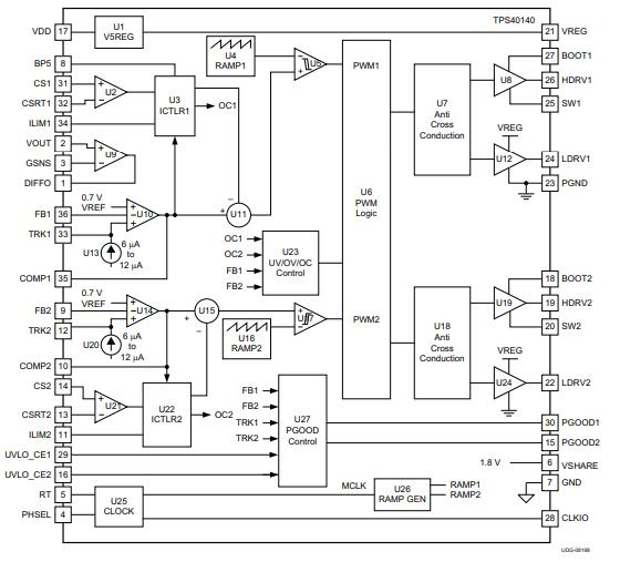
The functional block diagram of TPS40140RHHT is shown below:

TPS40140RHHT Functional Diagram
The following figures show the application circuits of TPS40140RHHT:
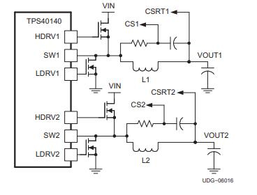
TPS40140RHHT Simplified Application Circuit
TPS40140RHHT Functional Diagram
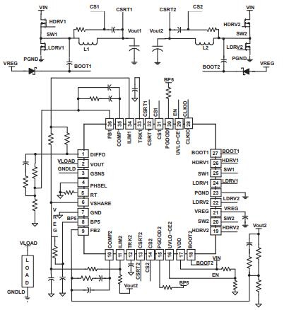
TPS40140RHHT Typical Applications Circuit, Dual Mode
| Attribute | Value |
|---|---|
| Lifecycle Status | NRND (Last Updated: 3 days ago) |
| Contact Plating | Gold |
| Mounting Type | Surface Mount |
| Package / Case | 36-VFQFN Exposed Pad |
| Surface Mount | YES |
| Number of Pins | 36 |
| Weight | 105.687022mg |
| Operating Temperature | -40°C~85°C TA |
| Packaging | Tape & Reel (TR) |
| JESD-609 Code | e4 |
| Pbfree Code | yes |
| Part Status | Not For New Designs |
| Moisture Sensitivity Level (MSL) | 2 (1 Year) |
| Number of Terminations | 36 |
| ECCN Code | EAR99 |
| Additional Feature | ALSO OPERATES IN CURRENT MODE |
| Terminal Position | QUAD |
| Peak Reflow Temperature (Cel) | 260 |
| Terminal Pitch | 0.5mm |
| Frequency | 1MHz |
| Base Part Number | TPS40140 |
| Function | Step-Down |
| Number of Outputs | 2 |
| Output Voltage | 5.8V |
| Output Type | Transistor Driver |
| Max Output Current | 25A |
| Attribute | Value |
|---|---|
| Input Voltage-Nom | 12V |
| Analog IC - Other Type | DUAL SWITCHING CONTROLLER |
| Output Configuration | Positive |
| Output Current | 25A |
| Voltage - Supply (Vcc/Vdd) | 4.5V~15V |
| Quiescent Current | 2.8mA |
| Control Features | Current Limit, Frequency Control, Phase Control, Power Good, Tracking |
| Max Output Voltage | 5.8V |
| Topology | Buck |
| Min Input Voltage | 2V |
| Control Mode | VOLTAGE-MODE |
| Frequency - Switching | 150kHz~1MHz |
| Max Input Voltage | 40V |
| Control Technique | PULSE WIDTH MODULATION |
| Synchronous Rectifier | Yes |
| Min Output Voltage | 700mV |
| Switcher Configuration | PHASE-SHIFT |
| Duty Cycle (Max) | 87.5% |
| Clock Sync | No |
| Height | 1mm |
| Length | 6mm |
| Width | 6mm |
| Thickness | 900μm |
| REACH SVHC | No SVHC |
| RoHS Status | ROHS3 Compliant |
| Lead Free | Lead Free |
Download datasheets and manufacturer documentation for