Difference between sg3525 and TL494 (Who is Winner Lts Find Out).???
IC REG CTRLR BCK/PUSH-PULL 16DIP
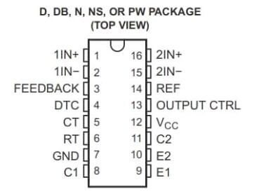
The TL494 IC is a fixed frequency current-mode PWM controller IC with all the functions that are required in the construction of the pulse-width modulation (PWM) control circuit on a single chip. This article will introduce TL494 systematically from its features, pinout to its specifications, applications, and so much more.