PCF8574 I2C GPIO Expander Tutorial
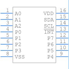
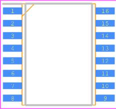
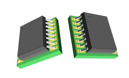
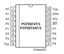
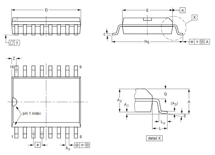
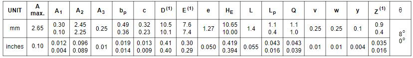
NXP PCF8574T/3,512 I/O Expander, 8bit, 100 kHz, I2C, 2.5 V, 6 V, SOIC
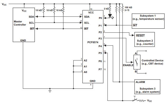
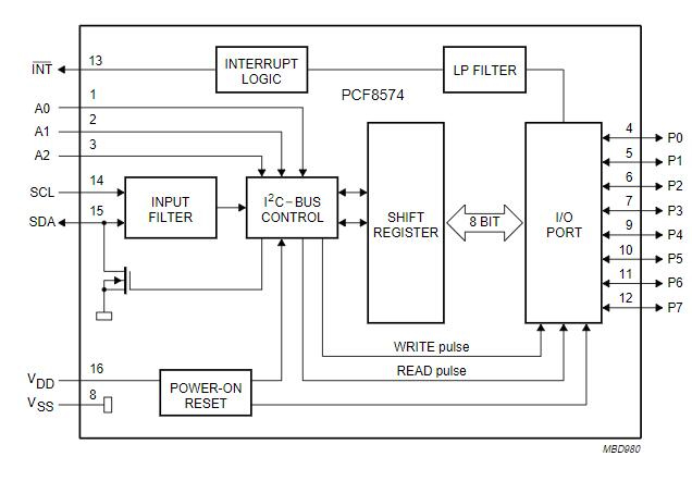
PCF8574T is a remote 8-bit I/O expander for I2C-bus made by NXP Semiconductors. What do you want to know about it? PCF8574T datasheet? PCF8574T applications? PCF8574T Manufacturer? PCF8574T circuit? PCF8574T package? OK, Magi will tell them all for you.